Power SMPS

Expand your power

Category: Power Supply

  • How to select a bridge rectifier diode

    How to select a bridge rectifier diode

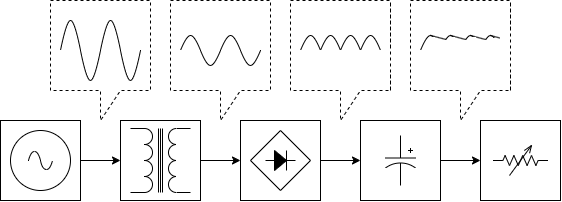
    Characteristics of Diodes

    As shown in the figure, a diode is a component that can allow current to flow only in the direction of ▶. This is a nonlinear relationship in which the forward current \( V_{F} \) rapidly increases when a voltage is applied across the diode above the forward voltage \( V_{F} \). In addition, when the forward current \( I_{F} \) flows, a forward voltage drop \( V_{F} \) must occur.

    Since power loss occurs at this time, attention should be paid to component heating in a high-current rectification circuit. When the diode is heated, leakage current increases, and there is a risk of fire due to thermal runaway. Therefore, most diode plastic molds meet the flame retardant standard of UL94V-0 or higher.

    Diode Forward Voltage(\( V_{F} \)) – Forward Current(\( I_{F} \))Characteristic

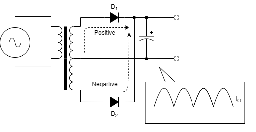
    Select the Reverse Maximum Voltage \(V_{RM}\) of the bridge diode

    In the bridge rectification circuit, while the diode is conducting, the applied voltage \( e\) of each diode terminal voltage \(V_{D}\) becomes \(\sqrt{2}\times e_{rms}\). In reality, if the input voltage of the AC fluctuates, \( e_{rms}\) also changes in proportion to it, so that \(V_{D}\) should not exceed the reverse maximum voltage \(V_{RM}\) of the diode even at the maximum input voltage.

    In addition, since the actual rectification circuit has the influence of external noise such as surges, \(V_{RM}\) should be selected sufficiently. In general, a Reverse voltage of twice the rectified voltage is selected, and if the applied voltage is unstable, a higher Reverse voltage selection is required.


    Selection of forward current \(I_{F}\) for bridge diode

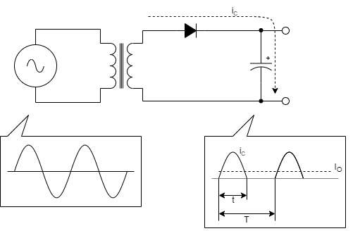
    In a typical rectifying circuit, the current \(i_{c}\) flowing through the diode flows in a pulse waveform rather than a sine wave. This pulse current has a maximum value that changes under various conditions.

    First, since the average value \(I_{ave}\) of \(i_{c}\) flowing through the diode must be equal to the DC current \(I_{O}\) after rectification, if the period of half-cycle is \(T\), and the period of current flowing is \(t_{1}\), it becomes \(\frac{1}{T}\int_{0}^{t_{1}}i_{c}dt=I_{0}\).

    Relation of RMS and Peak to Average Diode Current in Capacitor-input Circuits
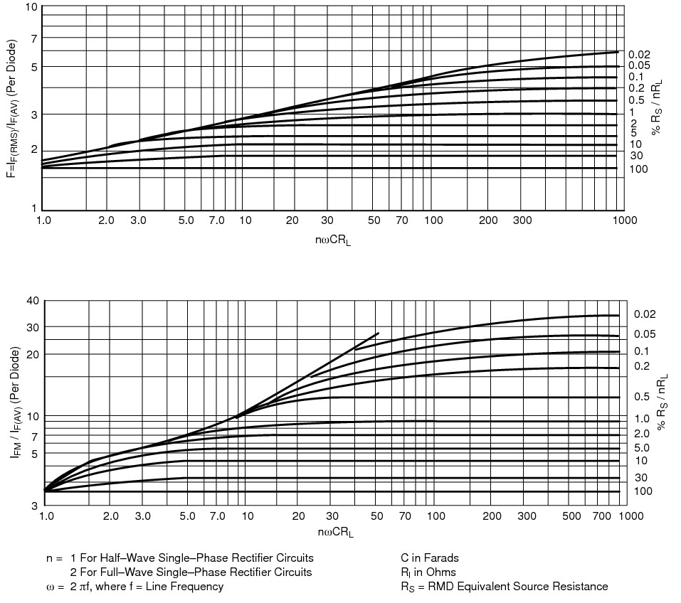
    From O.H Schade, Proc. IRE, Vol. 31, 1943, p. 356

    In general, the forward current \(I_{F}\) of a rectifying diode is maximum rated from the average value of this \(i_{c}\). However, this is the value when the current flows in direct current, and the pulse current should be considered low in the rated value. The maximum value \(i_{CP}\) of this pulsed current can be obtained from O.H. Schade’s graph. (n\) of \(n\omega CR_{L}\) on the horizontal axis has a coefficient of 0.5 at double voltage rectification, 1 at half-wave rectification, and 2 at full-wave rectification. \(C\) is the capacitor capacity, and \(R_{L}\) is the load resistance value.

    Next, \(R_{S}/\left ( nR_{L} \right )\) of the vertical axis means a ratio of the load resistance and the line impedance. The line impedance \(R_{S}\) should be considered to include not only the resistance value of the wiring but also the winding resistance of the power transformer.

    Under these conditions, the values of the left vertical axis are read from the graph below. This value multiplied by the output current \(I_{O}\) is the maximum current value \(i_{CP}\).


    Selection of diodes considering surge current

    Another current condition of the diode is surge current \(I_{FSM}\). In the rectifying circuit, when the power switch is initially operated, the charging voltage of the capacitor is set to 0V. Therefore, at the moment when the switch is operated, a large charging current flows to the capacitor. This is called the inrush current, and the terminal voltage of the capacitor is increased by this large charging current, and accordingly, the current value of the charging gradually becomes a normal state.

    In general, the surge current \(I_{FSM}\) of a rectifying diode has a value of about 10 times that of forward current \(I_{F}\). However, this is a guarantee value of one cycle and the value decreases when the temperature of the diode is high.


    Power loss of diode

    The diode suffers power loss due to the forward voltage drop \(V_{F}\) and the forward current \(I_{F}\). And as a result, it generates heat and increases the temperature. Silicon diodes currently in general must not exceed the maximum junction temperature \(T_{j(max)}\) 150℃. Since the current rating of the diode is determined under the condition of reaching the junction temperature, it is necessary to install a heatsink to lower the temperature when the temperature is high.

    It is not easy to calculate the power loss of a diode strictly. The simple calculation method is calculated by multiplying the output current \(I_{O}\) after rectification at the forward voltage drop \(V_{F}\) as the loss. In addition, in a bridge diode, the total loss should be doubled because current always flows through two diodes.

  • Type of rectifier according to the number of diodes

    Type of rectifier according to the number of diodes


    A half-wave rectifier with one diode

    Commercial power is a sinusoidal wave of 50/60 Hz, which is a symmetrical waveform of positive and negative voltages at every half of the frequency. Rectifying only a positive voltage with one diode is called a half-wave rectifier.

    At this time, the diode charges the capacitor with a positive voltage and prevents the charge in the opposite direction by reverse voltage to the diode in a negative voltage cycle. In this case, the direct current output current \( I_{O} \) is an average value of the capacitor charging current \( i_{C} \) and \( I_{O}=\frac{1}{T}\int_{0}^{t}i_{C}dt \).

    As such, in a half-wave rectifier, the charging current \(i_{C} \) of the capacitor is charged only once per cycle of the power supply frequency, so the current maximum \(i_{C,peak} \) gets that big. Therefore, if the output current is large, the half-wave rectifier has a large capacitor to reduce the output ripple. Therefore, it should only be used in circuits with small output currents.

    Half-wave rectifier

    A full-wave rectifier with two diodes

    The full-wave rectifier uses two diodes to rectify both positive and negative voltages of sine waves. A full-wave rectifier using two diodes requires two windings around the center tap of the transformer on the secondary side. In each transformer winding, diode \(D_{1}\) turn-on in the positive half cycle, and diode \(D_{2}\) turn-on in the negative half cycle. Therefore, the rectified waveform is a pulse waveform in which the negative half-period of the sine wave is inverted.

    Full-wave rectifier

    A full-wave rectifier with four diodes(Bridge Diode)

    The most commonly used is a full-wave rectifier using four diodes, also called a bridge rectifier. Four diodes should be used instead of one trans-winding, but it is not a big drawback because many bridge diodes with four diodes packaged are on the market.

    The current in the positive and negative half cycles alternately charges the capacitor, so it is fully rectified, but two diodes are inserted in series in the current path, which doubles the forward voltage drop \(V_{F} \) of the diode and increases the loss.

    For example, let calculate the efficiency of a 12W circuit with a rectified voltage of 12V and an output current of 1A. If the forward voltage drop \(V_{F} \) of the diode is 1V, for full-wave rectification using the center tap,

    $$\eta = \frac{12W}{\left ( 12V + 1V_{F} \right )\times 1A}=92\%$$

    For full-wave rectifier using a bridge diode,

    $$\eta = \frac{12W}{\left ( 12V + 2V_{F} \right )\times 1A}=86\%$$

    There is a big difference in efficiency.

    Despite these shortcomings, bridge rectifier are widely used because the center tap of the transformer can be removed and the circuit can be simplified using commercially available bridge diodes.

    Bridge rectifier

    Use a rectifier suitable for the purpose of the circuit

    As above, each rectifier has clear disadvantages and advantages. If one diode is used, the circuit is simple, but because the charging current of the capacitor is large, it must be used for small output, and if two diodes are used, the efficiency is high, but the center tab of the transformer has to be designed. Bridge diodes are simple to design, but efficiency should be consider the forward voltage drop of the diodes.

    Recently, synchronous rectifier, which are methods of rectifying using FET instead of diodes, have been used for high efficiency, but this will be explained later.

  • What is the difference between a linear regulator and a switching regulator?

    What is the difference between a linear regulator and a switching regulator?


    Use a linear regulator if power stability is required

    Linear regulator, called series regulator or shunt regulator, are mainly used when precise voltages are needed or when small power is needed, and when the unit price of the product has to be lowered. Linear regulator have very small electrical noise generation in a simple circuit configuration and have a small output ripple voltage, allowing them to configure high-stability power sources.

    However, a linear regulator uses a transistor to create a difference between an input voltage and an output voltage, resulting in a large power loss when the output current is large. Since all power losses are generated by heat, heat dissipation measures such as heat sinks are needed not to exceed the rated operating temperature. Therefore, when high output is required, power loss increases, making it difficult to use.

    Disadvantages of Linear Regulator
    Disadvantages of Linear Regulator

    Use switching regulators when high efficiency power is required

    Switching regulators are mainly used when high-efficiency power is required or when circuits need to be miniaturized. For example, since heat loss in linear regulators can be solved by switching loss in switching regulators, the power conversion efficiency is high and the area required for heat dissipation is small.

    In addition, the lower the operating frequency, the larger the size of the power transformer, so the linear regulator that converts 50/60Hz, which is a commercial power source, has a big and heavy power transformer. On the other hand, switching regulators can make the operating frequency several tens of kHz or more, making the transformer used for power conversion smaller and lighter.

    In addition, the linear regulator must make a DC voltage by dropping and rectifying the voltage by a transformer of commercial power. Therefore, the output current flows through the rectifying circuit as it is, and the loss of the rectifier diode is large, and the smoothing capacitor must also be large. However, the switching regulator uses a direct current voltage that directly rectifies commercial power, so the loss of the rectifier diode is small due to the small current, and the smoothing capacitor can be used small with an operating frequency of several tens of kHz or more.

    However, switching regulators are complicated in circuit configuration and operation. In addition, measures to reduce noise caused by switching are needed.

    Linear RegulatorSwitching egulator
    Step Down(Buck)
    Step Up(Boost)
    Buck-Boost
    Invert
    O
    X
    X
    X
    X
    X
    X
    X
    EfficiencyLowHigh
    Output CurrentLowHigh
    NoiseLowHigh
    DesignSimpleComplicated
    CostLowMiddle

    Recently, switching regulators are mainly used

    Recently, circuit integration technology has developed, and circuits that require complex functions are implemented as one IC. Switching regulators are also able to configure high-efficiency switching regulators with only a few peripheral circuit configurations. Of course, the types of parts depending on the use are also subdivided.

    However, if the method of using such an IC is not accurate, it may cause accidents such as a decrease in reliability or damage to parts. Therefore, the design of switching regulators is very important.

    Examples of switching regulators by TI (link)
  • Why do electronic circuits need regulated power supply?

    Why do electronic circuits need regulated power supply?


    The electronic circuit operates on DC power

    All electronic devices require power supply through an AC 110V/220V voltage which is a commercial power system(or a battery) for the operation of the device. In addition, these electronic devices require stable power sources such as 3.3V, 5V, and 12V.

    Electronic devices supplied with power through commercial power supply convert and rectified voltage to the required value by the power transformer to create a DC voltage and use it in a circuit. However, in a rectified DC power source, the performance of the device cannot be fully demonstrated because the stability and precision of the voltage are not good due to changes in the input voltage or a voltage drop of a transformer or rectifier diode.


    Causes of voltage fluctuations

    Quality of commercial power supply voltage

    Commercial power fluctuations exist even in countries with very good power systems using sufficient costs for power plants, etc. Most of them have small fluctuations of around ±5%, but some countries under development have a very large voltage drop of more than 10-20V.

    Power Transformer Voltage Drop

    Although it depends on the size of the transformer, a voltage drop occurs depending on the resistance of the wire because the copper wire is wound more than hundreds of times. In addition, since the leakage inductance between the primary and secondary of the transformer is inserted in series, a voltage drop occurs.

    Voltage drop in rectifier diode

    Bridge diodes, which are widely used for rectification, have forward voltage drops depending on the current

    Ripple Voltage

    Since the AC voltage of the commercial power source is sinusoidal, ripple voltage occurs due to charging and discharging even if it is smooth with a rectifier capacitor. This is represented by voltage fluctuations of twice the frequency in the case of full-wave rectification. In addition, when a load fluctuation occurs, a larger ripple voltage fluctuation occurs due to the imbalance of charging and discharging of the rectifier capacitor.

    full_wave_rectifier
    Full-wave rectifier

    Electronic circuits require a rated voltage

    All electronic components, such as motors and relays, as well as semiconductors such as ICs, have a rated voltage that is recommended to be used and a maximum voltage that guarantees operation. Therefore, if the voltage value is exceeded, the electronic component may not operate as designed, have a shorter lifespan, or may be damaged.

    For example, the rated voltage of most TTL ICs is 5V, the voltage that guarantees the operation is 4.5 to 5.5V, and the maximum voltage is 6 to 7V. In addition, in signal amplification circuits such as OPAMP, supply voltage fluctuations become signal fluctuations or noise. As a result, the designed precision or stability cannot be obtained.

    As such, the fluctuation of the power voltage is a problem to be solved in terms of the performance and reliability of the device. Therefore, power stabilization and regulated power supply are required through circuit design