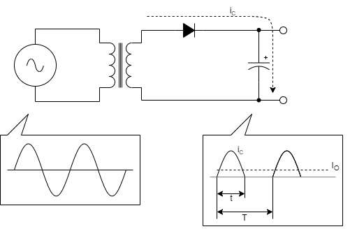
A half-wave rectifier with one diode
Commercial power is a sinusoidal wave of 50/60 Hz, which is a symmetrical waveform of positive and negative voltages at every half of the frequency. Rectifying only a positive voltage with one diode is called a half-wave rectifier.
At this time, the diode charges the capacitor with a positive voltage and prevents the charge in the opposite direction by reverse voltage to the diode in a negative voltage cycle. In this case, the direct current output current \( I_{O} \) is an average value of the capacitor charging current \( i_{C} \) and \( I_{O}=\frac{1}{T}\int_{0}^{t}i_{C}dt \).
As such, in a half-wave rectifier, the charging current \(i_{C} \) of the capacitor is charged only once per cycle of the power supply frequency, so the current maximum \(i_{C,peak} \) gets that big. Therefore, if the output current is large, the half-wave rectifier has a large capacitor to reduce the output ripple. Therefore, it should only be used in circuits with small output currents.
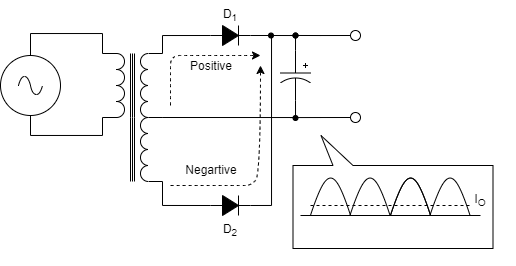
A full-wave rectifier with two diodes
The full-wave rectifier uses two diodes to rectify both positive and negative voltages of sine waves. A full-wave rectifier using two diodes requires two windings around the center tap of the transformer on the secondary side. In each transformer winding, diode \(D_{1}\) turn-on in the positive half cycle, and diode \(D_{2}\) turn-on in the negative half cycle. Therefore, the rectified waveform is a pulse waveform in which the negative half-period of the sine wave is inverted.
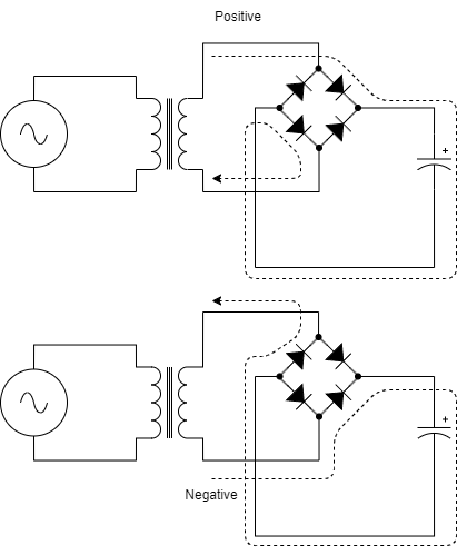
A full-wave rectifier with four diodes(Bridge Diode)
The most commonly used is a full-wave rectifier using four diodes, also called a bridge rectifier. Four diodes should be used instead of one trans-winding, but it is not a big drawback because many bridge diodes with four diodes packaged are on the market.
The current in the positive and negative half cycles alternately charges the capacitor, so it is fully rectified, but two diodes are inserted in series in the current path, which doubles the forward voltage drop \(V_{F} \) of the diode and increases the loss.
For example, let calculate the efficiency of a 12W circuit with a rectified voltage of 12V and an output current of 1A. If the forward voltage drop \(V_{F} \) of the diode is 1V, for full-wave rectification using the center tap,
$$\eta = \frac{12W}{\left ( 12V + 1V_{F} \right )\times 1A}=92\%$$
For full-wave rectifier using a bridge diode,
$$\eta = \frac{12W}{\left ( 12V + 2V_{F} \right )\times 1A}=86\%$$
There is a big difference in efficiency.
Despite these shortcomings, bridge rectifier are widely used because the center tap of the transformer can be removed and the circuit can be simplified using commercially available bridge diodes.
Use a rectifier suitable for the purpose of the circuit
As above, each rectifier has clear disadvantages and advantages. If one diode is used, the circuit is simple, but because the charging current of the capacitor is large, it must be used for small output, and if two diodes are used, the efficiency is high, but the center tab of the transformer has to be designed. Bridge diodes are simple to design, but efficiency should be consider the forward voltage drop of the diodes.
Recently, synchronous rectifier, which are methods of rectifying using FET instead of diodes, have been used for high efficiency, but this will be explained later.