After replacing a 6-pole compressor with a 8-pole unit, conducted emission (CE) noise at 150kHz increased under 2kHz DPWM inverter drive conditions. The fact that noise dropped significantly when compressor operation was stopped or when the protective earth (PE) was disconnected led to tracing the common-mode current return path. Compliance with the regulatory limit was achieved by winding the PE line with 10 or more turns on a ferrite core.
This post documents the root cause identified during that test, the reasons why rejected countermeasures were not adopted, and the items that must be re-verified before mass production.
Table of Contents
Test Conditions and Problem Symptoms
| Item | Condition / Symptom |
|---|---|
| Inverter control | 2kHz switching frequency, DPWM method |
| Compressor change | 6-pole motor replaced with 8-pole motor |
| Problem frequency band | 150kHz CE noise increase |
| Diagnostic result 1 | Noise greatly reduced when compressor drive is stopped |
| Diagnostic result 2 | Noise greatly reduced when product PE is disconnected |
PE disconnection is a diagnostic condition used to confirm the common-mode current path. Removing the protective earth cannot be used as a product-level countermeasure.
Root Cause of Increased 150kHz Noise
150kHz Falls in the 75-th Harmonic Region of 2kHz Switching
The relationship between 150kHz and the switching frequency is as follows.
\[\frac{150\,\mathrm{kHz}}{2\,\mathrm{kHz}}=75\]Therefore, the 150kHz band where the problem appeared corresponds to the 75-th harmonic region of the 2kHz switching frequency.
Furthermore, when the number of motor poles increases from 6 to 8 at the same rotational speed, the electrical frequency increases by 33.3%. This creates conditions in which the ratio of the fundamental to the switching frequency decreases and the sideband energy around the harmonics changes.
Increased Ground Parasitic Capacitance of the 8-Pole Motor
The 8-pole motor has a different winding and slot structure. This change was analyzed as having increased the ground parasitic capacitance \(C_g\) between the stator winding and the compressor enclosure.
The common-mode current flowing to ground during switching can be described by the following relationship.
\[I_{cm}=C_g\times\frac{dv}{dt}\]Even with the same \(dv/dt\), a larger \(C_g\) results in increased common-mode current.
Common-Mode Noise Return Path
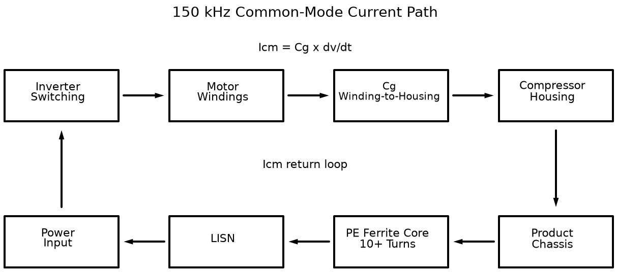
The closed loop inferred from the test results follows this sequence.
Inverter switching device → Motor winding → Cg → Compressor enclosure → Product chassis → PE → LISN → Power supply stage
The significant reduction in 150kHz noise observed when compressor operation was stopped or PE was disconnected supports the conclusion that this path is dominant.
Countermeasures Considered and Adoption Status
| Item Considered | Decision | Rationale |
|---|---|---|
| PE-line ferrite core winding | Adopted | Winding 10 or more turns secured sufficient impedance in the 150kHz band to suppress the ground-return common-mode current and meet the regulatory limit |
| Y-Cap value change | Not adopted | Because noise couples directly through the compressor enclosure and product chassis, the PCB power-stage Y-Cap cannot adequately bypass the chassis-loop current |
| Gate resistance \(R_g\) increase | Not adopted | \(dv/dt\) can be reduced, but it is difficult to maintain the switching-loss reduction objective of the 2kHz DPWM and stay within thermal limits |
| Direct bonding between compressor and PCB | Not adopted | The distance between the compressor and the main PCB makes it impractical to implement a low-inductance braided-wire connection |
The general role and selection criteria for Y-Caps are covered in SMPS Y-Cap: EMC and Audible Noise. In this case, the noise path differed, so a Y-Cap change was not adopted.
Selected Countermeasure: PE-Line Ferrite Core 10+ Turns
The final countermeasure is to insert a ferrite core in the PE line and wind the ground wire with 10 or more turns. The multi-turn winding raises the impedance in the 150kHz band and suppresses the high-frequency common-mode return current through the PE. The CE regulatory limit was satisfied in testing after this countermeasure was applied.
Applying the same 10-turn condition to other products requires re-verification based on the core characteristics and the actual noise path of each product.
Three Checks Before Mass Production
Protective Earth Continuity and Heat Generation
The report recommends verifying the following items during the ground continuity test, in which 25A to 32A is applied in accordance with safety standards such as IEC/EN 60335.
- Whether ground resistance satisfies 0.1Ω or less
- Whether heat is generated in the ground wire inside the core
- Mechanical integrity of the winding and terminal sections
The values above are the inspection criteria presented in the report; the actual compliance determination for the product must be made by consulting the latest applicable safety standards and test conditions for that product.
Full CE and RE Re-Scan
Winding 10 or more turns increases the inter-turn parasitic capacitance. In practice, this effect caused noise to rise again in the CE band above several MHz or in the radiated emission (RE) band of 30MHz to 1GHz.
Do not verify only the single 150kHz point; remeasure the full CE and RE spectrum.
Mechanical Countermeasure Against Compressor Vibration
Continued compressor vibration can cause friction between the ferrite core edges and the ground wire insulation. The following protective measures should also be considered.
- Taping the inner diameter of the core
- Reinforcing the ground wire with heat-shrink tubing
- Applying a core-fixing holder
- Inspecting for insulation damage after vibration endurance testing
Summary
This 150kHz CE problem was analyzed as a consequence of the 8-pole compressor change altering the electrical frequency and winding structure, which increased the common-mode return current through the parasitic capacitance between the winding and the enclosure. After narrowing down the path through the compressor-stop and PE-disconnection tests, winding the PE-line ferrite core with 10 or more turns raised the impedance in the 150kHz band and achieved compliance with the regulatory limit.
Before applying this solution in mass production, ground continuity and heat generation, the full CE and RE spectrum, and abrasion of the ground wire insulation due to vibration must all be verified together. When applying the solution to other products, re-confirm the frequency characteristics of the core and the common-mode return path specific to each product.
Leave a Reply