Smoothing capacitor lifetime cannot be evaluated solely from datasheet hour ratings. When evaluating a PCBA operating at high temperatures, the crucial criteria to verify firsthand are whether the temperature was measured under actual high-temperature conditions, and which input in the manufacturer’s lifetime formula that temperature corresponds to. Values obtained with an open board at room temperature must never be applied directly to the high-temperature operating conditions of the finished product.
Temperatures must be measured directly using thermocouples, while also analyzing the heat flow from bridge diodes, SMPS power semiconductor devices, transformers, and heatsinks. Separately from lifetime calculations, the potential for short circuits with adjacent components or the chassis upon pressure vent actuation must also be evaluated. Based on this design experience, this article outlines the lifetime evaluation procedure for non-solid aluminum electrolytic smoothing capacitors using liquid electrolyte.
Table of Contents
- Smoothing Capacitor Lifetime Calculations Begin by Verifying Datasheet Test Conditions
- Three Temperatures to Measure on a High-Temperature PCBA
- Contact and Operating Condition Replication Are Critical When Measuring with Thermocouples
- Component Placement Considering Convection from Bridge Diodes and Heatsinks
- Vent Clearance: Operating Margin and Secondary (2nd) Short-Circuit Prevention Are Evaluated Separately
- Comparison of Relative Lifetime Ratios with Decreasing Temperature
Smoothing Capacitor Lifetime Calculations Begin by Verifying Datasheet Test Conditions
In aluminum electrolytic capacitors, electrolyte gradually dissipates through the end seal during operation, which can cause capacitance to decrease and dielectric losses to increase. In typical smoothing circuits, ambient temperature and self-heating due to ripple current are the critical factors in lifetime evaluation. You must first verify the endurance test conditions of the selected series—including temperature, applied voltage, ripple current superposition, and end-of-life criteria. Nippon Chemi-Con Lifetime Technical Document
A practical approximation formula describing the effect of temperature is given below. However, this equation alone does not calculate the final product lifetime reflecting all ripple current conditions.
\[L_x=L_o\times B_t^{(T_o-T_x)/10}\]Here, \(L_o\) is the specified lifetime under datasheet test conditions, and \(L_x\) is the estimated lifetime under operating conditions. \(T_o\) is the upper category temperature, \(T_x\) is the actual ambient temperature defined in the manufacturer’s model, and \(B_t\) is the temperature acceleration factor. Corrections for ripple self-heating and applicable limits must be verified using product-specific lifetime formulas or calculation tools.
The commonly cited rule of thumb that ‘when temperature drops by 10°C, lifetime approximately doubles (2x)’ is an approximation assuming \(B_t=2\). Nippon Chemi-Con explains this approximation over an ambient temperature range of roughly 60~95°C, noting that products with maximum operating temperatures of 105°C or higher may require coefficient corrections depending on the estimated temperature range. You should never apply the same coefficient across all series and temperature ranges, nor should calculation results be interpreted as guaranteed lifetime.
For basic selection of capacitance, rated voltage, and permissible ripple current, it is helpful to cross-reference our previous article, How to Select Smoothing Capacitors.
Three Temperatures to Measure on a High-Temperature PCBA
For PCBAs operating at elevated temperatures, the fundamental principle is to take measurements under replicated operating conditions. Maintain the actual chassis, enclosure covers, mounting orientation, and cooling conditions, and record expected input, output, and load conditions. For continuous-duty products, evaluate conditions only after temperatures have fully stabilized. Do not assume that maximum load alone represents the most severe thermal condition for all components; define test conditions tailored to the product’s actual operating envelope.
Before plugging values into a lifetime equation, you must distinguish between the following three temperatures. The ambient temperature description below is based on Nippon Chemi-Con’s measurement definitions; always verify the definitions provided by the specific manufacturer selected for your application.
| Category | Definition | Key Considerations in Lifetime Evaluation |
|---|---|---|
| Ambient Temperature | The temperature at the specific mounting location influenced by external convection, radiation, and conduction, excluding self-heating of the capacitor | Cannot be assumed to be equal to room ambient air temperature |
| Case Surface Temperature | Temperature measured on the capacitor outer can during operation | Reflects both ambient thermal effects and internal self-heating, so it must not be directly substituted as ambient temperature |
| Core Temperature | Temperature of the internal capacitor element | Must not be assumed identical to surface temperature; evaluate according to manufacturer-approved methodologies |
Power loss due to ripple current can be approximated as follows. Because the resulting internal temperature rise directly impacts lifetime, one must not conclude the design is safe based solely on a low ambient temperature.
\[P\approx I_{\mathrm{rms}}^2\times\mathrm{ESR}\]Entering the operating surface temperature into the ambient temperature field while adding ripple self-heating again can result in double-counting thermal rise. Conversely, one should never omit evaluating internal temperature simply because surface temperature appears acceptable. The first step is to record whether each measured value corresponds to ambient, surface, or core temperature, and align it with the input definitions of the manufacturer’s lifetime model.
Contact and Operating Condition Replication Are Critical When Measuring with Thermocouples
Directly measuring temperatures used for lifetime evaluation with thermocouples is critical. However, using a thermocouple does not automatically guarantee accurate measurements. You must verify sensor contact and mechanical fastening, instrument calibration status, and electrical insulation. Documenting the attachment location alongside test conditions ensures that thermal performance before and after layout modifications can be compared on the same baseline.
Nippon Chemi-Con introduces a methodology that uses thermal imaging to identify locations under high thermal stress, followed by dummy capacitors and multiple thermocouples to evaluate external thermal influences excluding self-heating. The key principle is never to label operating can surface values directly as ambient temperature. For detailed specialized measurement procedures, follow the manufacturer’s guide to ambient temperature measurement.
Opening chassis covers or altering fan and ducting configurations to route thermocouple leads alters the actual thermal environment. Even after attaching sensors, you must recreate the final assembled enclosure and cooling conditions, verifying that temperatures reach steady state. Sensor attachment points should conform to manufacturer guidelines, and stabilization soak time must be determined based on when the system reaches true thermal equilibrium.
Sensor attachment and repositioning must be performed only after disconnecting power and verifying that residual voltages are fully discharged. When measuring power supply sections, verify insulation integrity across the sensors, instrumentation, and cabling. Never attempt to measure internal temperatures by modifying capacitor construction or probing charged terminals directly.
Component Placement Considering Convection from Bridge Diodes and Heatsinks
Smoothing capacitors are typically surrounded by heat-generating components such as bridge diodes, SMPS power semiconductors, and transformers (TRANS). Experience shows that checking physical clearance between components is not enough. You must also trace the pathways through which heat escaping from heat-generating components and their heatsinks reaches the capacitor.
Thermal flow paths differ significantly between natural convection and forced-air cooling, and product mounting orientation exerts a major influence. Verify that the capacitor does not lie in the exhaust path of hot air discharged from heatsinks based on the actual installed orientation. After modifying the component layout, remeasure under identical operating conditions to verify that thermal stress has been reduced.
In addition to convection, radiative heat transfer and thermal conduction through the PCB must be considered. Nichicon advises against placing heat-dissipating components near electrolytic capacitors or directly beneath capacitors on the reverse side of the board. The more constrained the layout area, the more critical it is to jointly examine surrounding heat sources and cooling airflow paths. Nichicon Application Guidelines
Vent Clearance: Operating Margin and Secondary (2nd) Short-Circuit Prevention Are Evaluated Separately
Failure conditions where internal pressure rises due to electrolyte vaporization or gas generation must be taken into account. The pressure vent is a safety mechanism designed to mitigate the risk of violent case rupture caused by excessive internal pressure buildup. In engineering practice, designers must evaluate whether deformed can sections will contact adjacent components or the chassis upon vent opening, and whether venting electrolyte can bridge conductors and cause electrical short circuits.
Examples of minimum top clearance above the vent recommended by Nippon Chemi-Con are outlined below. Individual product specifications and exceptions must be consulted first. These dimensions represent mechanical clearance to avoid impeding vent operation; they do not guarantee electrical insulation or safety against electrolyte expulsion. Pressure Vent and Top Space Guidelines
| Case Outer Diameter | Example Minimum Top Clearance Above Vent |
|---|---|
| 8 mm (some 6.3 mm products) to 16 mm | 2 mm or more |
| 18~35 mm | 3 mm or more |
| 40 mm or more | 5 mm or more |
Nichicon instructs that circuit traces and wiring must not be routed over the vent, explaining that because electrolyte is conductive, contact with the PCB creates risks of smoke and fire due to trace corrosion or short circuits. Therefore, design reviews must not stop at verifying overhead clearance dimensions; the actual vent orientation and expected spray paths must also be investigated.
In the final layout, designers must jointly evaluate vent opening orientation, expansion deformation envelope, component and chassis locations with assembly tolerances, potential electrolyte dispersion paths, operating voltages, and finished-product safety requirements. Electrical clearance and creepage distances are entirely separate considerations from vent mechanical clearance. Because no single safety spacing rule applies universally across all mechanical enclosures, the final clearance must be determined based on component manufacturer data and the specific product architecture.
A clear distinction must also be made between end-of-life dry-up and vent actuation caused by abnormal pressure buildup. Gradual wear-out degradation, where electrolyte loss leads to decreased capacitance and increased loss tangent, does not necessarily culminate in vent opening. Lifetime calculations evaluate parametric degradation, whereas layout reviews serve to mitigate secondary (2nd) damage during fault events such as vent actuation.
Comparison of Relative Lifetime Ratios with Decreasing Temperature
The following is an educational calculation assuming \(B_t=2\) with all other conditions held constant. It does not represent actual measurement data or guaranteed lifetimes for a specific product. Relative lifetime ratios were calculated based on temperature reduction relative to a baseline. The applicable temperature range and ripple corrections must be verified for each specific product series.
\[\frac{L}{L_{\mathrm{ref}}}=2^{\Delta T_{\mathrm{red}}/10}\]| Assumed Temperature Reduction | Calculated Relative Lifetime Ratio |
|---|---|
| 0°C | 1x |
| 10°C | 2x |
| 20°C | 4x |
| 30°C | 8x |
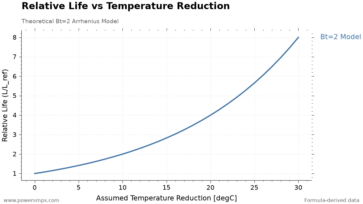
This comparison illustrates why engineers verify operating temperatures with thermocouples and scrutinize the placement of heat sources. In practical design, one must not apply these multiplier ratios directly to product lifetime simply because the temperature was reduced; always re-evaluate using the specific lifetime model for the chosen series.
When completing the design review, verify the following checklist items.
- Have high-temperature operating conditions, the actual chassis enclosure, mounting orientation, and cooling airflow been faithfully replicated?
- Have thermocouple mechanical contact, secure fastening, instrument calibration status, and electrical insulation been verified?
- Have ambient, case surface, and core temperatures been clearly distinguished, ensuring self-heating is not double-counted?
- Have the manufacturer’s series endurance test conditions and lifetime equation validity boundaries been confirmed?
- Has thermal airflow from bridge diodes, transformers, SMPS power semiconductors, and heatsinks been fully considered?
- Have vent operational clearance and clearance to prevent short circuits to adjacent components and the chassis been evaluated separately?
Leave a Reply